
Steam trap TB52
- SCCV system
- Suitable for condensate recovery
- Horizontal installation
- Vertical installation
- Option
– Customized flange
-
Completely closed
The temperature control trap enables adjustable subcooling of the condensate. This maintains a specific condensate level in the trap. The mechanism is 100% leak-proof, which effectively prevents steam loss during operation.
-
Suitable for high pressures, high temperatures and superheated steam
-
Outstanding durability
The MIYAWAKI SCCV system (Self Closing and Centering Valve) is characterized by a significantly longer service life thanks to the reduced closing forces.
The freely rotating valve always sits optimally in the valve guide, even under the extreme conditions that prevail in high-pressure applications, as it is centered and guided by the condensate flow. This design significantly reduces stress and therefore wear on the valve components. -
Fast commissioning
Discharges the cold condensate and cold air quickly.
Also functions as a deaerator.
-
Energy savings
Controlling the temperature of the discharged condensate ensures significant energy savings.
-
Low operating noise and very low formation of flash steam
Typical applications
Suitable for steam main lines, steam tracing and other similar applications.
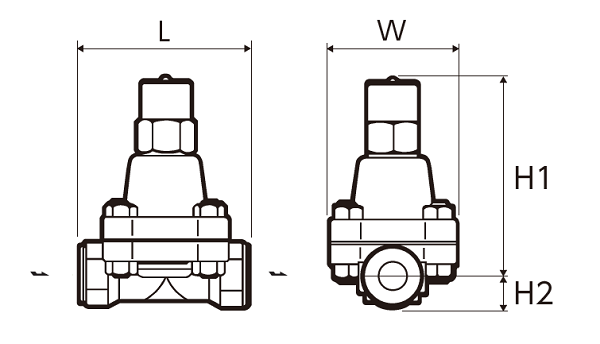
Threaded socket/welding socket
Here is the customized table based on the template you provided:
| Nominal width | Dimensions (mm) | Weight (kg) |
|||
|---|---|---|---|---|---|
| L | H1 | H2 | W | ||
| 1/2″ | |||||
| 3/4″ | 130 | 155 | 25 | 100 | 5,7 |
| 1″ | |||||
Flange
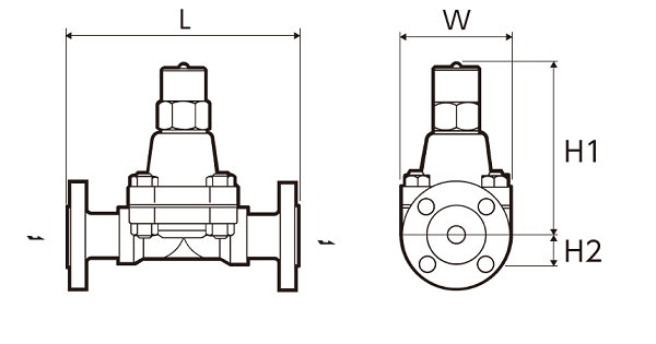
| Nominal width | Flange standards | Dimensions (mm) | Weight | ||||
| L | H1 | H2 | W | (kg) | |||
| 1/2″ | JIS (RF) |
20K | 200 | 155 | 25 | 100 | 7,3 |
| 30K | 8,4 | ||||||
| 40K | 8,7 | ||||||
| 63K | 220 | 9,6 | |||||
| ASME/JPI (RF) |
150lb | 200 | 6,7 | ||||
| 300lb | 7,2 | ||||||
| 600lb | 7,3 | ||||||
| 900lb | 220 | 9,6 | |||||
| 3/4″ | JIS (RF) |
20K | 210 | 7,7 | |||
| 30K | 8,9 | ||||||
| 40K | 9,2 | ||||||
| 63K | 230 | 11,1 | |||||
| ASME/JPI (RF) |
150lb | 210 | 7,7 | ||||
| 300lb | 8,2 | ||||||
| 600lb | 8,5 | ||||||
| 900lb | 230 | 10,9 | |||||
| 1″ | JIS (RF) |
20K | 240 | 9,2 | |||
| 30K | 10,1 | ||||||
| 40K | 10,5 | ||||||
| 63K | 12,1 | ||||||
| ASME/JPI (RF) |
150lb | 8,3 | |||||
| 300lb | 9,4 | ||||||
| 600lb | 9,6 | ||||||
| 900lb | 13,3 | ||||||
| DN15 | DIN PN63/PN100 | 210 | 155 | 25 | 100 | 9,4 | |
| DN20 | 230 | 11,4 | |||||
| DN25 | 12,1 | ||||||
* Customized dimensions on request.
| Model | Connection | Max. Operating pressure (bar) | Max. Differential pressure (bar) | Max. Operating temperature (℃) | Setting range (℃) | Default setting (℃) | Housing material | |
|---|---|---|---|---|---|---|---|---|
| Type | Nominal size | |||||||
| TB52-45 | Threaded socket Rc,NPT |
1/2″ | 45 | 45 | 475 | 100 – 220 | 180 (at 21 bar) | Chrome-molybdenum steel A182 F22 |
| 3/4″ | ||||||||
| 1″ | ||||||||
| TB52-65 | 1/2″ | 65 | 65 | 100 – 240 | 220 (at 44 bar) | |||
| 3/4″ | ||||||||
| 1″ | ||||||||
| TB52F-45 | Flange RF |
1/2″ | 45 | 45 | 100 – 220 | 180 (at 21 bar) | ||
| 3/4″ | ||||||||
| 1″ | ||||||||
| TB52F-65 | 1/2″ | 65 | 65 | 100 – 240 | 220 (at 44 bar) | |||
| 3/4″ | ||||||||
| 1″ | ||||||||
| TB52W-45 | Welding socket SW |
1/2″ | 45 | 45 | 100 – 220 | 180 (at 21 bar) | ||
| 3/4″ | ||||||||
| 1″ | ||||||||
| TB52W-65 | 1/2″ | 65 | 65 | 100 – 240 | 220 (at 44 bar) | |||
| 3/4″ | ||||||||
| 1″ | ||||||||
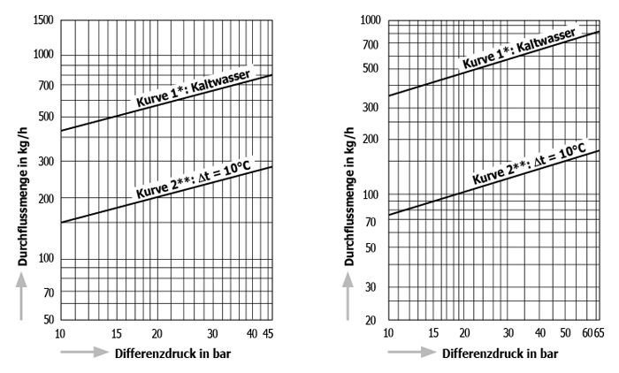
● ⊿t is the difference between the temperature of a temperature control trap when the valve is first opened and the temperature of the condensate. The temperature difference (⊿t) at the first flow of air is large and indicates that the flow rate will also increase.
* Curve 1 shows the maximum capacity of the trap when discharging cold condensate.
** Curve 2 shows the maximum capacity of the trap when discharging hot condensate with a temperature of 10 °C below the setpoint temperature of the trap.
