Steam trap TB9BN-R
- SCCV system
- Suitable for condensate recovery
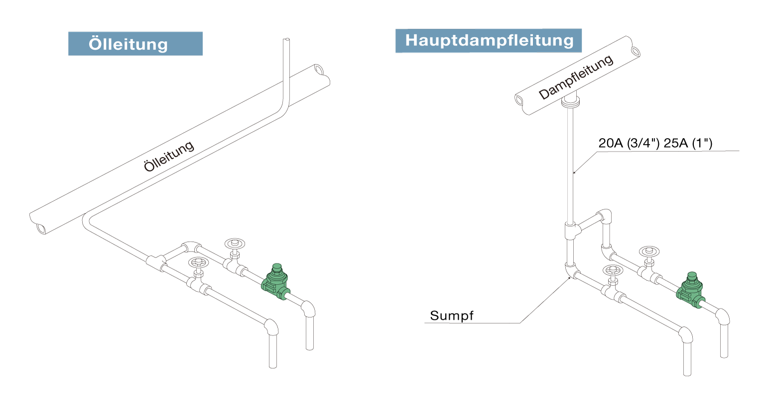
- Horizontal installation
- Vertical installation
- Option
– Customized flange
-
Completely closed
The temperature control trap enables adjustable subcooling of the condensate. This maintains a specific condensate level in the trap. The mechanism is 100% leak-proof, which effectively prevents steam loss during operation.
-
Outstanding durability
The MIYAWAKI SCCV system (Self Closing and Centering Valve) is characterized by a significantly longer service life thanks to the reduced closing forces. The freely rotating valve always sits optimally in the valve guide, even under the extreme conditions that prevail in high-pressure applications, as it is centered and guided by the condensate flow. This design significantly reduces stress and therefore wear on the valve components.
-
Energy savings
Controlling the temperature of the discharged condensate ensures significant energy savings. In particular, if the sensible heat of the condensate can be used for heating in applications, the trap significantly reduces steam consumption.
-
Blowdown valve
A blowdown valve can be used to remove sludge and scale that has penetrated the pipes without having to dismantle the trap.
● TB9BN-C for up to 9.8 bar
Typical applications
Suitable for main steam pipes as well as trace and tank heating systems, building heating systems and similar applications.
Threaded socket/welding socket
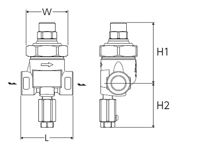
| Nominal width | Dimensions (mm) | Weight (kg) | |||
|---|---|---|---|---|---|
| L | H1 | H2 | W | ||
| 1/2″ | 70 | 82 | 60 | 56 | 1,0 |
| 3/4″ | 80 | 1,1 | |||
| 1″ | 1,2 | ||||
Flange
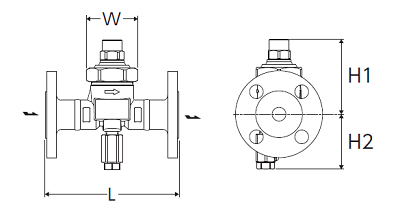
JIS,ASME
| Nominal width | Dimensions (mm) | Weight (kg) | |||
|---|---|---|---|---|---|
| L | H1 | H2 | W | ||
| 1/2″ | 70 | 82 | 60 | 56 | 1,0 |
| 3/4″ | 80 | 1,1 | |||
| 1″ | 1,2 | ||||
* Customized dimensions on request.
* Please contact MIYAWAKI if you require further information.
| Model | Connection | Max. Operating pressure (bar) | Max. Differential pressure (bar) | Max. Operating temperature (℃) | Setting range (℃) | Default setting (℃) | Housing material | |
|---|---|---|---|---|---|---|---|---|
| Type | Nominal size | |||||||
| TB9BN-R | Threaded socket Rc,NPT |
1/2″ | 16 | 16 | 350 | 50 – 180 | 100 (at 5bar) |
Forged steel A105 |
| 3/4″ | ||||||||
| 1″ | ||||||||
| TB9BNF-R | Flange FF,RF* |
1/2″ | ||||||
| 3/4″ | ||||||||
| 1″ | ||||||||
| TB9BNW-R | Welding socket SW |
1/2″ | ||||||
| 3/4″ | ||||||||
| 1″ | ||||||||
* Available flange standards: ASME/JPI 150lb, 300lb, DIN PN40, JIS 10K, 16K, 20K
● Max. permissible pressure (PMA): 40 bar PMA is the design pressure of pressure-resistant parts (housing).
● Max. permissible temperature (TMA): 400 ℃ TMA is the design temperature of pressure-resistant parts (housing).
● Min. operating differential pressure (⊿PMN): 0.1 bar ⊿PMN is the minimum operating differential pressure between the inlet and outlet of the condensate drain.
* The factory-set standard temperature can be changed. Please enter the operating pressure and set temperature.
* Information on adjusting the setpoint temperature can be found in the installation instructions.
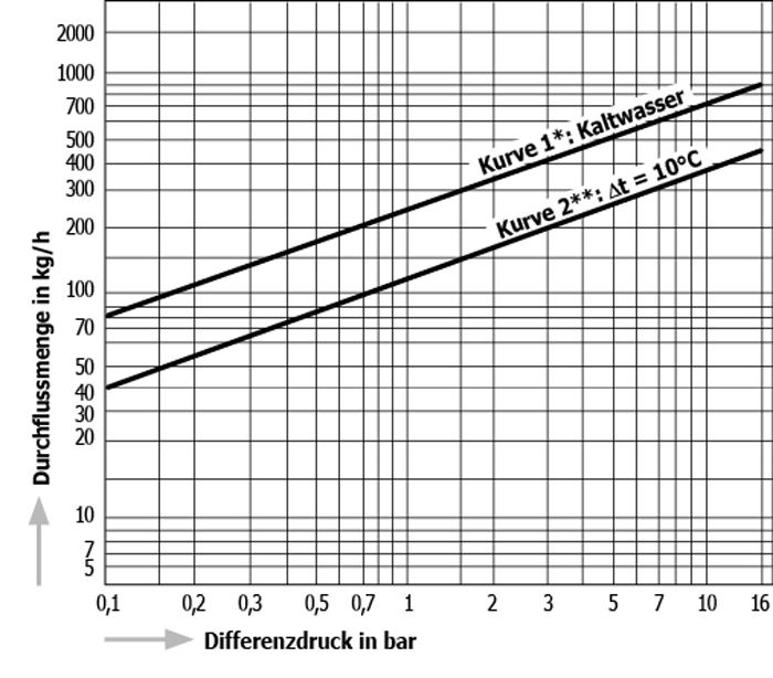
● ⊿t is the difference between the temperature of a temperature control trap when the valve is first opened and the temperature of the condensate.
The temperature difference (⊿t) at the first flow of air is large and indicates that the flow rate will also increase.
* Curve 1 shows the maximum capacity of the trap when discharging cold condensate.
** Curve 2 shows the maximum capacity of the trap when discharging hot condensate with a temperature of 10 °C below the setpoint temperature of the trap.