Steam trap TB9N-SR
- SCCV system
- Suitable for condensate recovery
- Horizontal installation
- Vertical installation
- Option
– Customized flange
-
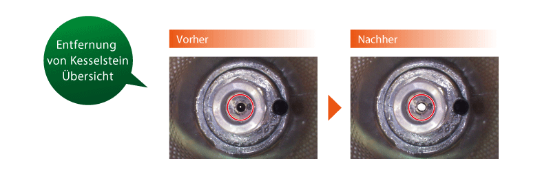
Scale can be removed 10 times faster than with conventional models.
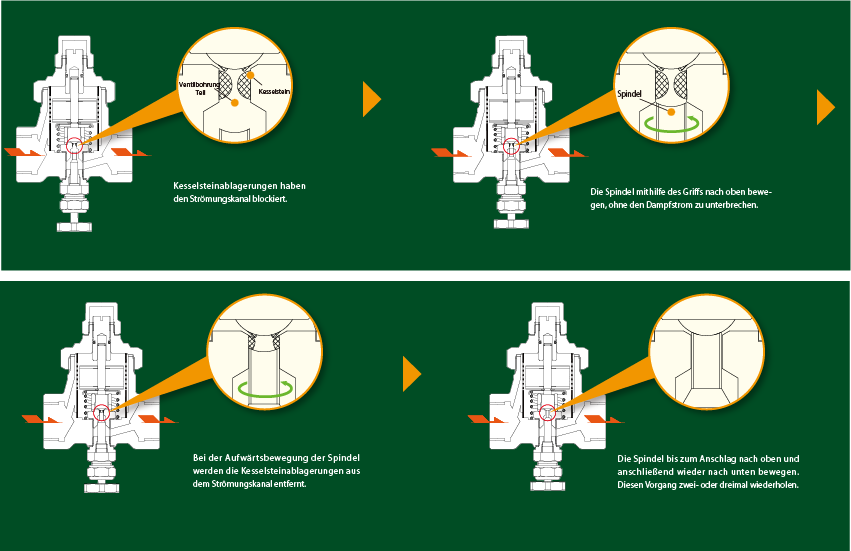
Disassembly before cleaning is no longer necessary. Scale is removed immediately by simply turning a handle without having to interrupt the steam flow. This only takes around 3 minutes per trap.
-
Removal of scale from the flow channel
Large quantities of scale are deposited in the flow channel (inlet and outlet opening of the valve) of temperature control traps. Scale is removed below the valve opening so that the scale can be completely removed.
-
Preventive measures to ensure the locking function
This product enables efficient, regular removal of scale. Regular removal prevents scale from impairing the closing function.
-
Outstanding durability
The MIYAWAKI SCCV system (Self Closing and Centering Valve) is characterized by a significantly longer service life thanks to the reduced closing forces
The freely rotating valve always sits optimally in the valve guide, even under the extreme conditions that prevail in high-pressure applications, as it is centered and guided by the condensate flow. This design significantly reduces stress and therefore wear on the valve components.
Suitable for steam main lines, steam tracing and other similar applications.
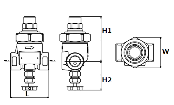
Threaded socket/welding socket
| Nominal width | Dimensions (mm) | Weight | |||
|---|---|---|---|---|---|
| L | H1 | H2 | W | (kg) | |
| 1/2″ | 70 | 82 | 54 | 56 | 1,0 |
| 3/4″ | 80 | 1,1 | |||
| 1″ | 1,2 | ||||
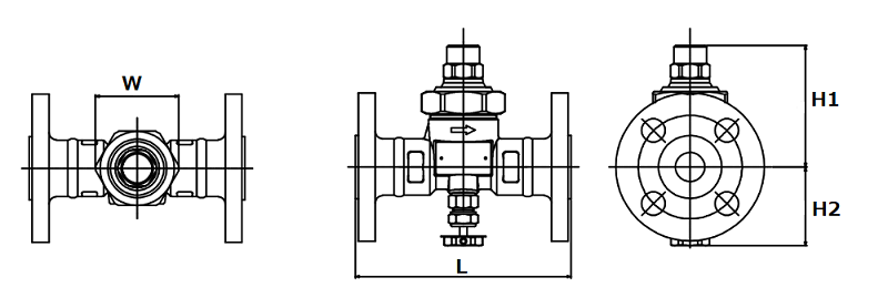
Flange
JIS,ASME
| Nominal width | Dimensions (mm) | Weight (kg) | |||||||
|---|---|---|---|---|---|---|---|---|---|
| L | H1 | H2 | W | JIS (FF, RF) | JIS (RF) | ASME/JPI (RF) | |||
| 10K, 16K | 20K | 30K | 150lb | 300lb | |||||
| 1/2″ | 145 | 82 | 54 | 56 | 2,5 | 2,6 | 2,7 | 2,1 | 2,6 |
| 3/4″ | 2,9 | 3,0 | 3,1 | 2,6 | 3,5 | ||||
| 1″ | 4,0 | 4,2 | 4,3 | 3,3 | 4,3 | ||||
DIN PN40
| Nominal width | Dimensions (mm) | Weight (kg) | |||||||
|---|---|---|---|---|---|---|---|---|---|
| L | H1 | H2 | W | JIS(FF,RF) 10K,16K |
JIS(FF,RF) 20K |
JIS(RF) 30K |
ASME/JPI(RF) 150lb |
ASME/JPI(RF) 300lb |
|
| 1/2″ | 145 | 82 | 54 | 56 | 2,5 | 2,6 | 2,7 | 2,1 | 2,6 |
| 3/4″ | 2,9 | 3,0 | 3,1 | 2,6 | 3,5 | ||||
| 1″ | 4,0 | 4,2 | 4,3 | 3,3 | 4,3 | ||||
| Nominal width | Dimensions (mm) | Weight (kg) | |||
|---|---|---|---|---|---|
| L | H1 | H2 | W | ||
| DN15 | 150 | 82 | 54 | 56 | 2,7 |
| DN20 | 3,5 | ||||
| DN25 | 160 | 4,1 | |||
* Customized dimensions on request.
* Customized dimensions on request.
| Model | Connection | Max. Operating pressure (bar) | Max. Differential pressure (bar) | Max. Operating temperature (℃) | Setting range (℃) | Default setting (℃) | Housing material | |
|---|---|---|---|---|---|---|---|---|
| Type | Nominal size | |||||||
| TB7N-SR | Threaded socket Rc , NPT |
1/2″ | 21 | 21 | 230 | 50 – 200 | 100 (at 10 bar) |
Forged steel A105 |
| 3/4″ | ||||||||
| 1″ | ||||||||
| TB7NF-SR | Flange FF, RF |
1/2″ | ||||||
| 3/4″ | ||||||||
| 1″ | ||||||||
| TB7NW-SR | Welding socket | 1/2″ | ||||||
| 3/4″ | ||||||||
| 1″ | ||||||||
* Horizontal and vertical piping possible. A downward slope ensures that the condensate can easily run into the condensate drain.
* The factory-set standard temperature can be changed. Please enter the operating pressure and set temperature.
* Information on adjusting the setpoint temperature can be found in the installation instructions.
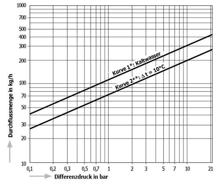
● ⊿t is the difference between the temperature of a temperature control trap when the valve is first opened and the temperature of the condensate.
● The temperature difference (⊿t) at the first flow of air is large and indicates that the flow rate will also increase.
* Curve 1 shows the maximum capacity of the trap when discharging cold condensate.
** Curve 2 shows the maximum capacity of the trap when discharging warm condensate with a temperature of 10 °C below the setpoint temperature of the trap.
[TB9N-SR Example]