
Steam trap G20N
- Suitable for condensate recovery
- Horizontal installation
- Automatic venting
-
Suitable for steam process lines
The float mechanism drains the condensate immediately and at saturation temperature, preventing the condensate from accumulating on the primary side. Ideal for applications where condensate must not be allowed to build up.
-
Faster commissioning
Discharges cold air and cold condensate automatically. The membrane capsule deaerator is controlled by the saturation temperature and prevents air and steam congestion.
-
Energy-saving design
Achieves high sealing performance even with extremely low condensate volumes and reduces steam loss thanks to a precision-polished float and a three-point support mechanism.
-
Condensate recovery
With its high back pressure tolerance, this model is suitable for condensate return.
Typical applications
Suitable for use in food appliances, cleaning equipment, air conditioning systems and similar applications.
Threaded sleeve
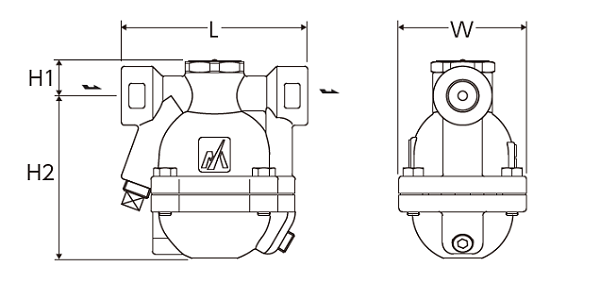
| Nominal width | Dimensions (mm) | Weight (kg) | |||
|---|---|---|---|---|---|
| L | H1 | H2 | W | ||
| 1/2″ | 120 | 24 | 105 | 82 | 2,5 |
| 3/4″ | |||||
| 1″ | 107 | 2,6 | |||
Flange
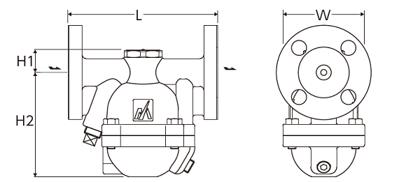
| Nominal width | Flange standards | Dimensions (mm) | Weight (kg) | |||
|---|---|---|---|---|---|---|
| L | H1 | H2 | W | |||
| 1/2″ | JIS (FF, RF) 10 K, 16 K, 20 K | 150 | 24 | 105 | 82 | 3,8 |
| ASME/JPI(RF) 150lb | 145 | 3,5 | ||||
| ASME/JPI(RF) 300lb | 150 | 3,8 | ||||
| 3/4″ | JIS (FF, RF) 10 K, 16 K, 20 K | 150 | 4,2 | |||
| ASME/JPI(RF) 150lb | 145 | 3,9 | ||||
| 1″ | JIS (FF, RF) 10 K, 16 K, 20 K | 160 | 5,3 | |||
| ASME/JPI(RF) 150lb | 157 | 4,6 | ||||
| DN15 | PN25 | 150 | 24 | 105 | 82 | 3,7 |
| DN20 | 4,2 | |||||
| DN25 | 160 | 4,8 | ||||
Specifications
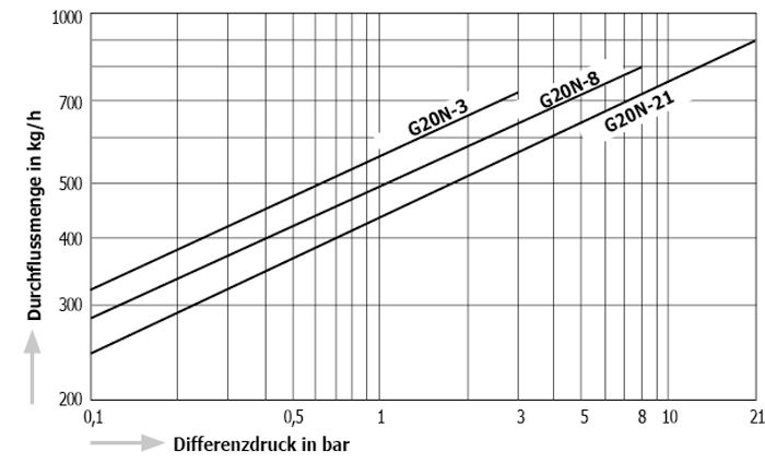
| Model | Connection | Max. Operating pressure (bar) | Max. Differential pressure (bar) | Max. Operating temperature (℃) | Venting type | Housing material | |
|---|---|---|---|---|---|---|---|
| Type | Nominal size | ||||||
| G20N-3 | Threaded socket Rc, NPT | 1/2″ | 3 | 3 | 220 | Spheroidal graphite cast iron FCD450 | |
| 3/4″ | |||||||
| 1″ | |||||||
| G20N-8 | Threaded socket Rc, NPT | 1/2″ | 8 | 8 | |||
| 3/4″ | |||||||
| 1″ | |||||||
| G20N-21 | Threaded socket Rc, NPT | 1/2″ | 21 | 21 | |||
| 3/4″ | |||||||
| 1″ | |||||||
| G20N-3F | Flange FF, RF | 1/2″ | 3 | 3 | |||
| 3/4″ | |||||||
| 1″ | |||||||
| G20N-8F | Flange FF, RF | 1/2″ | 8 | 8 | |||
| 3/4″ | |||||||
| 1″ | |||||||
| G20N-21F | Flange FF, RF | 1/2″ | 21 | 21 | |||
| 3/4″ | |||||||
| 1″ | |||||||
● Max. permissible pressure (PMA): 21 bar. PMA is the design pressure of pressure-resistant parts (housing).
Max. permissible temperature (TMA): 220 ℃. TMA is the design temperature of pressure-resistant parts (housing).
● Min. operating differential pressure (⊿PMN): 0.1 bar. ⊿PMN is the minimum operating differential pressure between the inlet and outlet of the condensate drain.
* Available flange standards: ASME/JPI, DIN, JIS
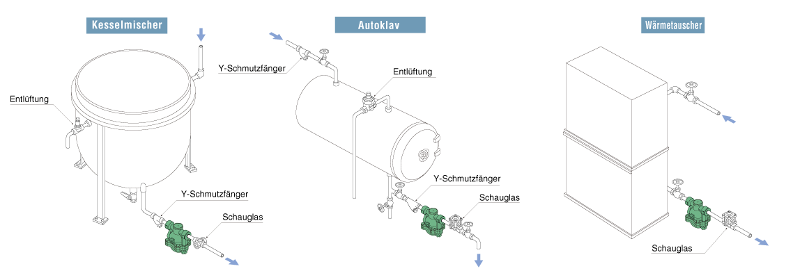
■ Associated product models for reference
Y strainer YM1
Sight glass TS1 T3
Air vent AT9N
