Steam trap G30 / NEW!
- Suitable for condensate recovery
- Horizontal installation
- Automatic venting
-
Suitable for steam process lines
The float mechanism drains the condensate immediately and at saturation temperature, preventing the condensate from accumulating on the primary side. Ideal for applications where condensate must not be allowed to build up.
-
Minimize steam losses, maximize ease of maintenance
Thanks to the high-precision ground float and the three-point support mechanism, high sealing performance is maintained even at low condensate levels and steam waste is minimized. The design with the top replaceable vent and uniform bottom cover allows for easy maintenance without removing the steam trap from the steam line.
-
Condensate recovery
With its high back pressure tolerance, this model supports condensate recovery. It reduces energy, water and waste water treatment costs.
-
Countermeasure against erosion
Use of stainless steel components at the outlet that are exposed to erosion by the condensate flow.
Three-point support mechanism
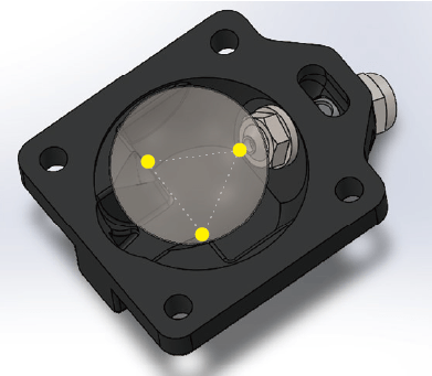
The stability of the float is maintained by three bases on the underside,
This ensures a high sealing performance and minimizes steam leakage.
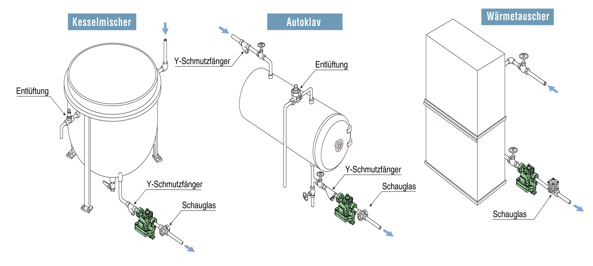
Typical applications
Suitable for use in food processing plants, cleaning equipment, air conditioning systems and other similar applications.
Threaded sleeve

| Nominal diameter | Connection size | Dimensions (mm) | Maintenance range (mm) | Weight (mm) | ||||
|---|---|---|---|---|---|---|---|---|
| L | H1 | H2 | W | E1 | E2 | kg | ||
| ¾” | Threaded socket (Rc) |
155 | 44 | 125 | 118 | 60 | 70 | 6,7 |
| 1″ | 6,5 | |||||||
| 1¼” | 160 | 6,4 | ||||||
| 1½” | 6,3 | |||||||
| ¾” | Threaded socket (NPT) |
155 | 44 | 125 | 118 | 60 | 70 | 6,7 |
| 1″ | 160 | 6,6 | ||||||
| 1¼” | 165 | 6,5 | ||||||
| 1½” | 6,3 | |||||||
Flange

| Nominal diameter | Connection size | Dimensions (mm) | Maintenance range (mm) | Weight (mm) | ||||
| L | H1 | H2 | W | E1 | E2 | kg | ||
| 1¼” | JIS(FF,RF) 10K,16K |
260 | 44 | 125 | 118 | 60 | 70 | 10,2 |
| JIS(FF,RF) 20K |
264 | 10,5 | ||||||
| ASME/JPI(RF) 150lb |
260 | 9,1 | ||||||
| 1½” | JIS(FF,RF) 10K,16K |
260 | 10,4 | |||||
| JIS(FF,RF) 20K |
264 | 10,8 | ||||||
| ASME/JPI(RF) 150lb |
260 | 10,0 | ||||||
| DN32 | PN25 | 230 | 10,1 | |||||
| DN40 | 10,9 | |||||||
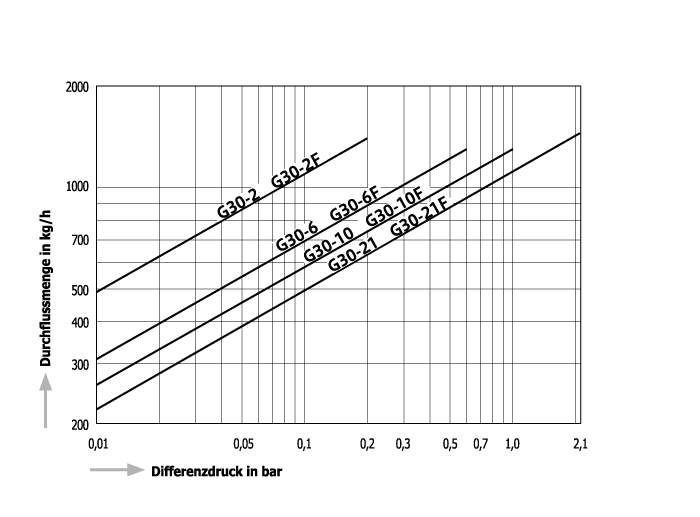
| Model | Connection | Max. operating pressure | Max. differential pressure | Max. Operating temperature | Housing material | |
|---|---|---|---|---|---|---|
| Type | Nominal diameter | (bar) | (bar) | (℃) | ||
| G30-2 | Threaded socket Rc,NPT |
¾” | 2 | 2 | 235 | Ductile iron FCD450 |
| 1″ | ||||||
| 1¼” | ||||||
| 1½” | ||||||
| G30-6 | ¾” | 6 | 6 | |||
| 1″ | ||||||
| 1¼” | ||||||
| 1½” | ||||||
| G30-10 | ¾” | 10 | 10 | |||
| 1″ | ||||||
| 1¼” | ||||||
| 1½” | ||||||
| G30-21 | ¾” | 21 | 21 | |||
| 1″ | ||||||
| 1¼” | ||||||
| 1½” | ||||||
| G30-2F | Flange FF,RF* |
1¼” | 2 | 2 | ||
| 1½” | ||||||
| G30-6F | 1¼” | 6 | 6 | |||
| 1½” | ||||||
| G30-10F | 1¼” | 10 | 10 | |||
| 1½” | ||||||
| G30-21F | 1¼” | 21 | 21 | |||
| 1½” | ||||||
● Max. permissible pressure (PMA): 25 bar PMA is the design pressure of pressure-resistant parts (housing).
● Max. permissible temperature (TMA): 250℃ TMA is the design temperature of pressure-resistant parts (housing).
● Max. Back pressure during operation (PMOB): 90 % of the pressure on the inlet side
*Available flange standards: JIS 10K,16K,20K, ASME/JPI 150lb, PN25
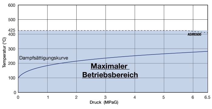
Max. Operating pressure and max. operating temperature
- PMO: 2.1MPa at 235℃
- TMO: 235℃ at 2.1MPa