
Steam trap GC1N / stainless steel
- Stainless steel
- Suitable for condensate recovery
- Horizontal installation
- Automatic venting
-
- Option
- – Customized flange
- – ASTM material available
-
No condensate build-up on the primary side (continuous condensate drainage due to self-regulated valve opening)
The float mechanism drains the condensate immediately and at saturation temperature, preventing the condensate from accumulating on the primary side. Ideal for applications where condensate must not be allowed to build up.
-
Outstanding sealing performance
Achieves high sealing performance and reduces steam loss thanks to a precision-polished float. The float is specially manufactured to meet the highest requirements for shape accuracy and surface tolerance. In combination with the specially lapped valve, MIYAWAKI offers one of the tightest free-floating ball steam trap designs on the market.
-
Automatic venting (due to built-in bimetal)
Discharges cold air and cold condensate automatically.
-
Compact design
The lever-free design consists of fewer components and therefore reduces the risk of defects and the associated maintenance and inspection costs.
-
Stainless steel
With the exception of the bimetal, all components are made of corrosion-resistant stainless steel, which is also highly resistant to contact with aggressive steam additives.
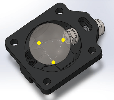
The stability of the float is maintained by three bases on the underside,
This ensures a high sealing performance and minimizes steam leakage.
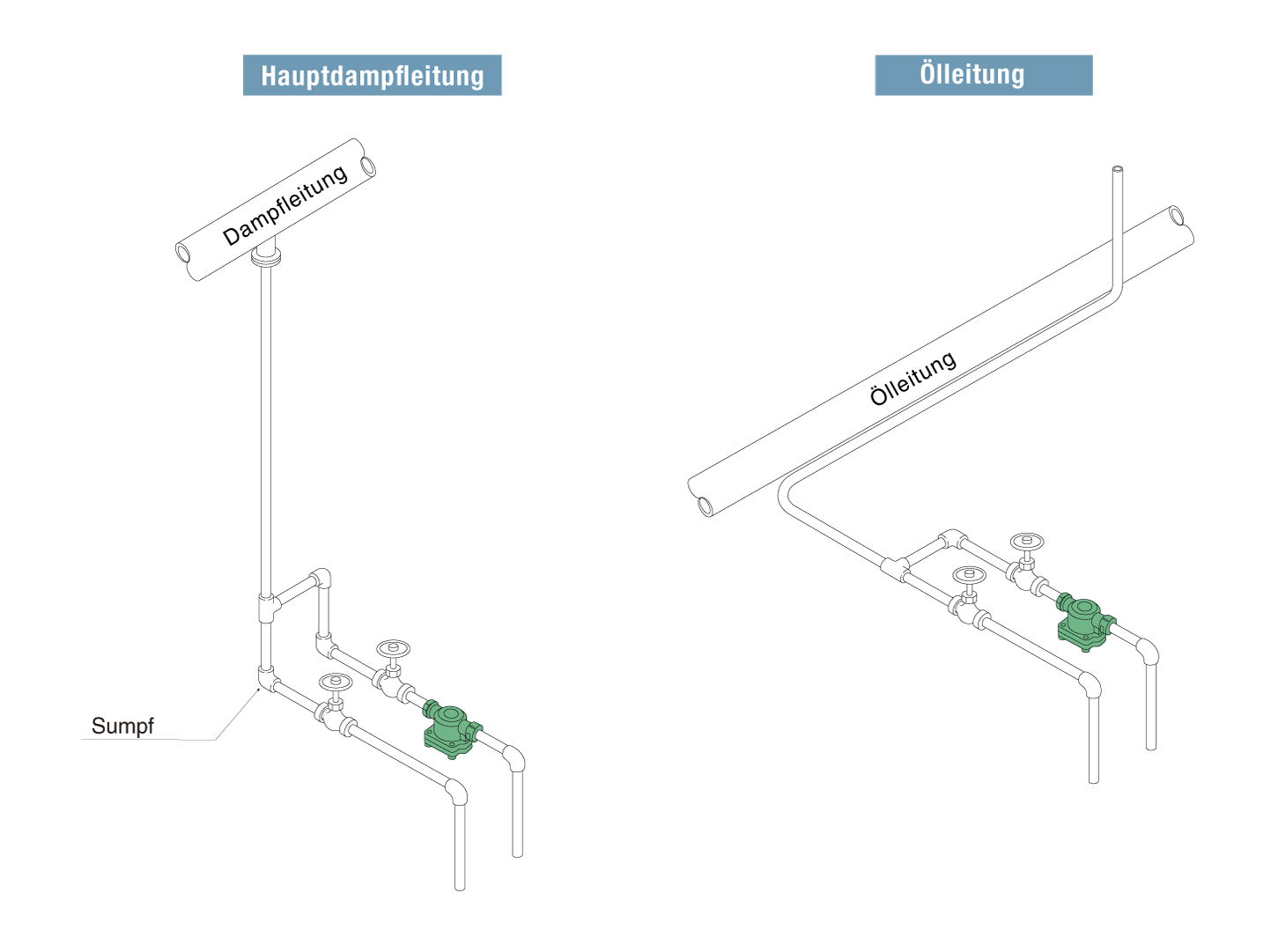
Typical applications
Suitable for steam main lines, steam trace heating systems, heat exchangers with small loads and similar applications.
Threaded sleeve
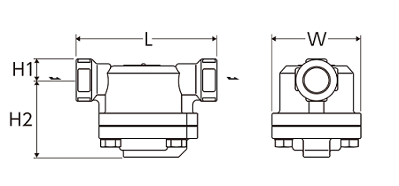
| Nominal width | Dimensions (mm) | Weight | |||
|---|---|---|---|---|---|
| L | H1 | H2 | W | (kg) | |
| 1/2″ | 127 | 15 | 75 | 86 | 1,8 |
| 3/4″ | 136 | 1,9 | |||
| 1″ | 140 | 2,0 | |||
Falnsch
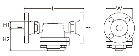
| Nominal width | Dimensions (mm) | Weight (kg) | |||||||
|---|---|---|---|---|---|---|---|---|---|
| L | H1 | H2 | W | ASME/JPI | DIN | JIS (FF) | JIS (RF) | ||
| 150lb | 300lb | PN40 | 10K,16K | 20K | |||||
| 1/2″ | 175 | 14 | 77 | 86 | 2,9 | 3,3 | 3,7 | 3,3 | 3,5 |
| 3/4″ | 195 | 3,5 | 4,5 | 4,4 | 3,8 | 4,0 | |||
| 1″ | 215 | 4,2 | 5,3 | 5,1 | 5,0 | 5,3 | |||
* Customized dimensions on request.
Welding socket
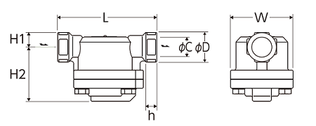
| Nominal width | Dimensions (mm) | Weight | ||||||
|---|---|---|---|---|---|---|---|---|
| L | H1 | H2 | W | D | C | h | (kg) | |
| 1/2″ | 127 | 15 | 75 | 86 | 36 | 22,2 | 15 | 1,8 |
| 3/4″ | 136 | 41 | 27,7 | 1,9 | ||||
| 1″ | 140 | 50 | 34,5 | 2,0 | ||||
| Model | Connection | Max. operating pressure | Max. differential pressure | Max. Operating temperature | Housing material | |
|---|---|---|---|---|---|---|
| Type | Nominal diameter | (bar) | (bar) | (℃) | ||
| GC1N-10 | Threaded socket Rc,NPT |
1/2″ | 10 | 10 | 350 | Cast stainless steel SCS13A/CF8 |
| 3/4″ | ||||||
| 1″ | ||||||
| GC1N-16 | 1/2″ | 16 | 16 | |||
| 3/4″ | ||||||
| 1″ | ||||||
| GC1N-21 | 1/2″ | 21 | 21 | |||
| 3/4″ | ||||||
| 1″ | ||||||
| GC1N-10F | Flange FF,RF |
1/2″ | 10 | 10 | ||
| 3/4″ | ||||||
| 1″ | ||||||
| GC1N-16F | 1/2″ | 16 | 16 | |||
| 3/4″ | ||||||
| 1″ | ||||||
| GC1N-21F | 1/2″ | 21 | 21 | |||
| 20 | ||||||
| 25 | ||||||
| GC1N-10W | Welding socket SW |
1/2″ | 10 | 10 | ||
| 3/4″ | ||||||
| 1″ | ||||||
| GC1N-16W | 1/2″ | 16 | 16 | |||
| 3/4″ | ||||||
| 1″ | ||||||
| GC1N-21W | 1/2″ | 21 | 21 | |||
| 3/4″ | ||||||
| 1″ | ||||||
● Max. permissible pressure (PMA): 21 bar PMA is the design pressure of pressure-resistant parts (housing).
● Max. permissible temperature (TMA): 350 ℃ TMA is the design temperature of pressure-resistant parts (housing).
● Min. operating differential pressure (⊿PMN): 0.1 bar ⊿PMN is the minimum operating differential pressure between the inlet and outlet of the condensate drain.
* Available flange standards: ASME/JPI, DIN, JIS

GC1N Horizontal installation
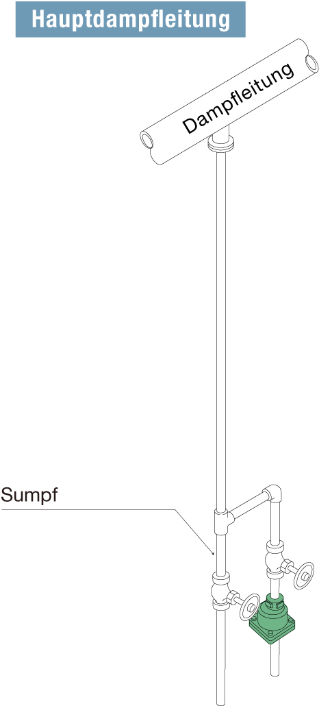
GC1V Vertical installation
