
Steam trap GTH12
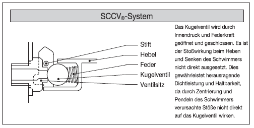
- SCCV system
- Suitable for condensate recovery
- Horizontal installation
- Automatic venting
-
- Option
- – Customized flange
- – ASTM material available
-
No condensate build-up on the primary side (float system with continuous drainage)
The float mechanism drains the condensate immediately and at saturation temperature, preventing the condensate from accumulating on the primary side. Ideal for applications where condensate must not be allowed to build up.
-
Outstanding sealing performance and durability
Offers excellent sealing performance and durability thanks to the SCCV system.
This mechanism developed by MIYAWAKI increases the durability of the valve and ensures maximum sealing performance. The housing is designed to withstand even high-pressure applications up to 50 barg.
-
No vapor or air entrapment
The installed air vent ensures fast commissioning. The air vent removes the cold condensate and prevents air and steam congestion.
-
Easy maintenance
All valve parts are attached to the inside of the hood, which makes maintenance quick and easy. The trap can be serviced without removal.
-
Condensate recovery
With its high back pressure tolerance, this model is suitable for condensate return.
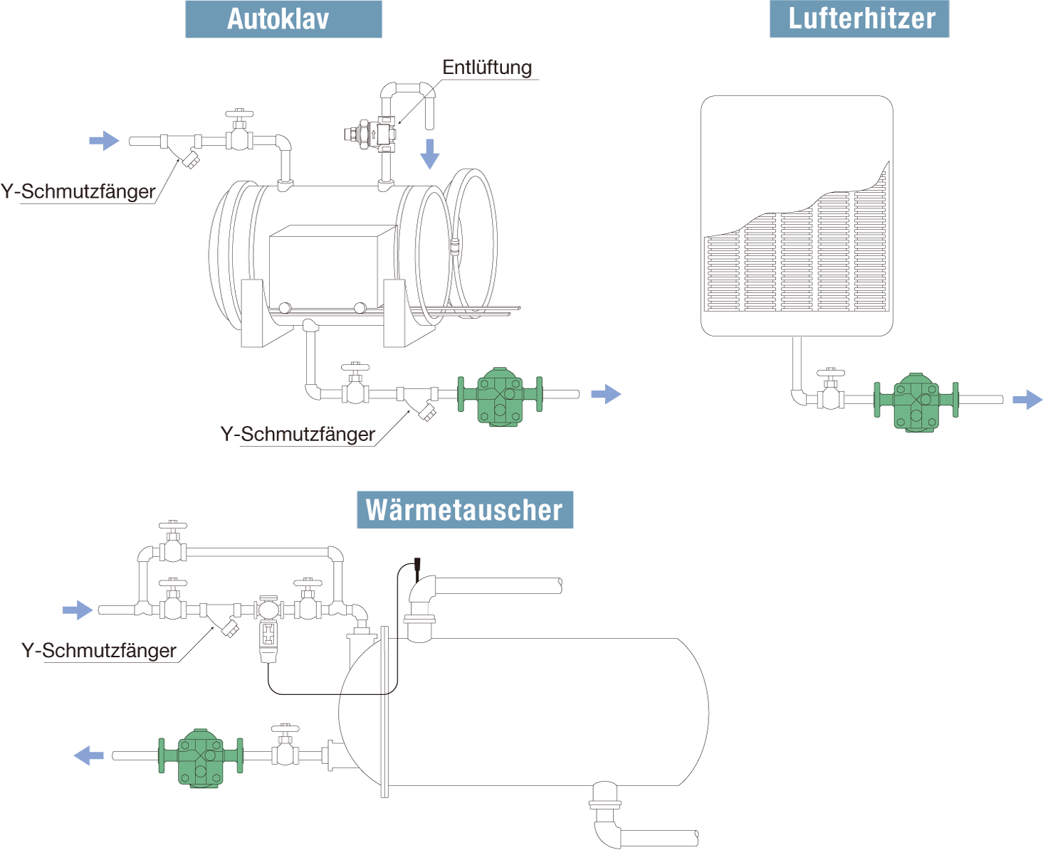
Typical applications
The trap is generally used in high-temperature steam pipes and process systems with medium to high pressure.
Flange

| Nominal width | Dimensions (mm) | Weight (kg) | ||||||||
|---|---|---|---|---|---|---|---|---|---|---|
| L | H1 | H2 | W1 | W2 | JIS (FF) | JIS (RF) | ASME/JPI (RF) | DIN | ||
| 10K,16K, 20K | 30K,40K | 150lb, 300lb | 600lb | PN16, PN40 | ||||||
| 1/2″ | 250 | 75 | 95 | 30 | 195 | 12,7 | 14,0 | 12,7 | 14,0 | 14,0 |
| 3/4″ | 13,5 | 14,2 | 13,5 | 14,2 | 14,2 | |||||
| 1″ | 14,0 | 15,2 | 14,0 | 15,2 | 15,2 | |||||
* Available flange standards: ASME/JPI, DIN, JIS
* Customized dimensions on request.
Welding socket

| Nominal width | Dimensions (mm) | Weight (kg) | ||||
|---|---|---|---|---|---|---|
| L | H1 | H2 | W1 | W2 | ||
| 1/2″ | 220 | 75 | 95 | 30 | 195 | 11,5 |
| 3/4″ | 11,6 | |||||
| 1″ | 11,7 | |||||
| Model | Connection | Max. Operating pressure (bar) | Max. Differential pressure (bar) | Max. Operating temperature (℃) | Housing material | |
|---|---|---|---|---|---|---|
| Type | Nominal size | |||||
| GTH12-5F | Flange FF,RF | 1/2″ | 32 | 5 | 400 | Cast steel SCPH2/WCB |
| 3/4″ | ||||||
| 1″ | ||||||
| GTH12-16F | 1/2″ | 16 | ||||
| 3/4″ | ||||||
| 1″ | ||||||
| GTH12-25F | 1/2″ | 25 | ||||
| 3/4″ | ||||||
| 1″ | ||||||
| GTH12-32F | 1/2″ | 32 | ||||
| 3/4″ | ||||||
| 1″ | ||||||
| GTH12-45F | 1/2″ | 50 | 45 | 425 | ||
| 3/4″ | ||||||
| 1″ | ||||||
| GTH12-5W | Welding socket SW | 1/2″ | 32 | 05 | 400 | |
| 3/4″ | ||||||
| 1″ | ||||||
| GTH12-16W | 1/2″ | 16 | ||||
| 3/4″ | ||||||
| 1″ | ||||||
| GTH12-25W | 1/2″ | 25 | ||||
| 3/4″ | ||||||
| 1″ | ||||||
| GTH12-32W | 1/2″ | 32 | ||||
| 3/4″ | ||||||
| 1″ | ||||||
| GTH12-45W | 1/2″ | 50 | 45 | 425 | ||
| 3/4″ | ||||||
| 1″ | ||||||
● Max. permissible pressure (PMA): 32 bar (GTH12-45: 50 bar)
● Max. permissible temperature (TMA): 400℃ (GTH12-45: 425℃)
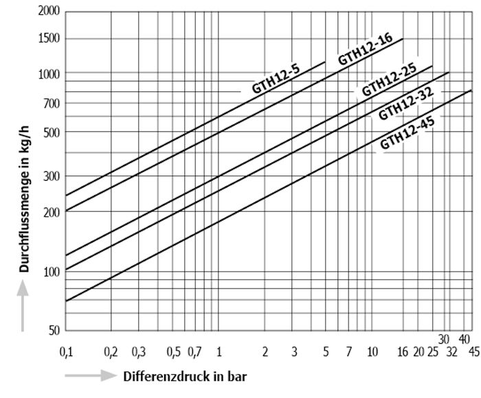
● Min. operating differential pressure (⊿PMN): 0.1 bar – ⊿PMN is the minimum operating differential pressure between the inlet and outlet of the condensate drain.
● Max. Back pressure during operation (PMOB): 90 % of the pressure on the inlet side
* Available flange standards: ASME/JPI, DIN, JIS
* Customized sizes 1 1/4″, 1 1/2″ and 2″ on request.
* ASTM material (WCB) and stainless steel (SCS13A) on request.
* Vertical installation on request.
* A version with reversed inlet and outlet direction is available on request.
■ Additional products for comparison
Y strainer: YM1
Air vent AT9N
